Category Archives: FPGA

More FPGA and NeoPixels

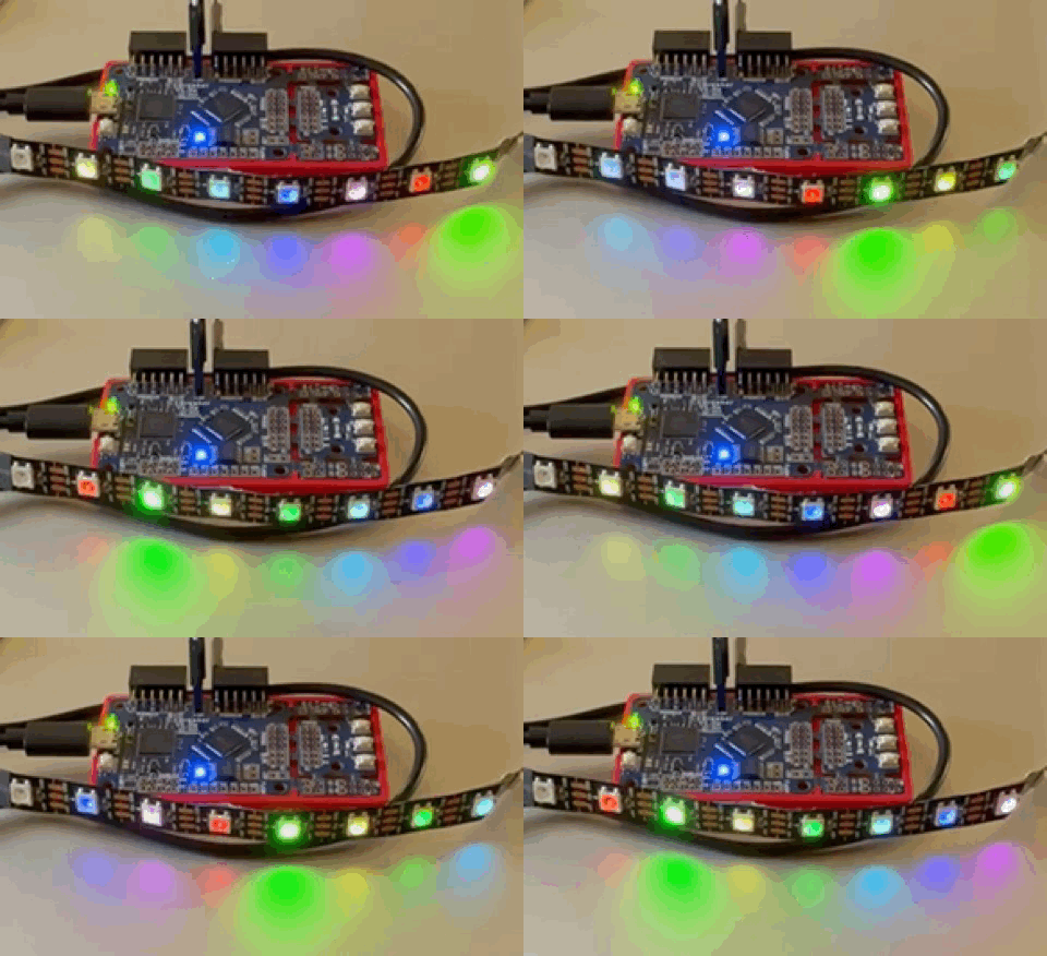
Animated colors with FPGA and WS2812b strip.

After understanding the code from Vivonomicon‘s post I was able to animate the colors in a section of an WS2812B strip using an Icebreaker FPGA.

I had originally thought that this project would not be so difficult to implement. Once I “got” the concepts I was able to create the animated colors. The following code includes lines from Vivonomicon.

// Cause yosys to throw an error when we implicitly declare nets
// `default_nettype none

// Project entry point
module top (
	input  CLK,
	input  BTN_N, BTN1, BTN2, BTN3,
	output LED1, LED2, LED3, LED4, LED5,
	output P1B1,
);
	// Neopixel state machine.
  reg [2:0] state;
  reg [1:0] npxc;
  reg [12:0] lpxc;
  reg [7:0] bits;
  reg [7:0] led_num;
  reg [24:0] test_color = 24'b000000010000000100000000;
	reg [1:0] isiton;
	reg [24:0] color_run1 = 24'b000000001000000000000000;
	reg [24:0] color_run2 = 24'b000000001000000000010000;
	reg [24:0] color_run3 = 24'b000000001000000010000000;
	reg [24:0] color_run4 = 24'b000000000000000010000000;
	reg [24:0] color_run5 = 24'b100000000000000010000000;
	reg [24:0] color_run6 = 24'b100000000000000000000000;
	reg [24:0] color_run7 = 24'b100000001000000000000000;
	reg [24:0] color_temp = 24'b000000001000000000000000;
	reg [32:0] running_it = 0;

	assign LED1 = 1'b0;
	assign LED2 = 1'b0;
	assign LED3 = 1'b0;
	assign LED4 = 1'b0;
	assign LED5 = 1'b0;
	assign P1B1 = isiton;

	always @(posedge CLK) begin
		// Process the state machine; states 0-3 are the four WS2812B 'ticks',
		// each consisting of 83.33 * 4 ~= 333.33 nanoseconds. Four of those
		// ticks are then ~1333.33 nanoseconds long, and we can get close to
		// the ideal 1250ns period.
		// A '1' is 3 high periods followed by 1 low period (999.99/333.33 ns)
		// A '0' is 1 high period followed by 3 low periods (333.33/999.99 ns)

		if (state == 0 || state == 1 || state == 2 || state == 3)
			begin									// run this for 3 times then increase state
				npxc = npxc + 1;
				if (npxc == 0)
					begin
						state = state + 1;
					end
			end // end of states 0, 1, 2, OR 3
		if (state == 4) // increases bits then if 24 set to 0 and increase state to 5, if <24 state = 0
			begin
				bits = bits + 1;
				if (bits == 24)
					begin
						bits = 0;
						state = state + 1;
					end
				else
					begin
						state = 0;
					end
			end // end of state 4
		if (state == 5) // go to the next pixel on the strip. if it is at the end state = 6, otherwise state = 0
			begin
				led_num = led_num + 1;
				case (led_num)
				1:	test_color = color_run1;
				2:	test_color = color_run2;
				3:	test_color = color_run3;
				4:	test_color = color_run4;
				5:	test_color = color_run5;
				6:	test_color = color_run6;
				7:	test_color = color_run7;
				default: test_color = 24'b000000000000000000000000;
				endcase
				if (led_num == 10)
					begin
						led_num = 0;
						state = state + 1;
					end
				else
					begin
						state = 0;
					end
			end // end of state 5
		if (state == 6) // This is a 12 bit counter sending 0 out the serial indicating reset of the strip
			begin					// it lasts for >80µs meaning that the end of the pixel numbers has been reached
				lpxc = lpxc + 1;
				if (lpxc == 0)
					begin
						state = 0;
					end
			end // end of state 6
		// Set the correct pin state.
		if (test_color & (1 << bits)) // if the current bit of test_color is 1, or ON, serial is high
			begin
			if (state == 0 || state == 1 || state == 2) //  run three cycles of high for pixel ON
				begin
					isiton <= 1;
				end
			else if (state == 3 || state == 6) // run one cycle of low for pixel ON
				begin
					isiton <= 0;
				end
			end // end of testing the & bit is 1. If the current bit is 0, or OFF, serial is low.
		else
			begin
			if (state == 0) // run one cycle of high for pixel OFF
				begin
					isiton <= 1;
				end
			else if (state == 1 || state == 2 || state == 3 || state == 6) // run three cycles of low for pixel off
				begin
					isiton <= 0;
				end
		end // end of testing the & bit is 0
	end // end of the always main program

	// make another always module to change the colors in a cycle
	always @(posedge CLK) begin
		running_it++;
		if (running_it == 1000000) begin
			running_it = 0;
			color_temp = color_run1;
			color_run1 = color_run2;
			color_run2 = color_run3;
			color_run3 = color_run4;
			color_run4 = color_run5;
			color_run5 = color_run6;
			color_run6 = color_run7;
			color_run7 = color_temp;
		end // end of the running_it and reset
	end // end of the always that cycles the color_run stuff

endmodule

There might be better ways of implementing the result, but I think I did pretty well as a beginner in FPGA land.

Now that I have this completed I might be able to add a different power source for the 5v on the WS2812B strip. Then I should be able to add more strips by using the other PMOD pins. This Icebreaker has three PMODs built on it. That would be 24 strips. It would make for a great animation.

In the mean time I could add the dip-switch PMOD and use the switches to determine the speed that the cycling lights run. At first I thought of using a potentiometer to control the speed. I have some, probably too many. The dip-switch module is sitting out right by where I have been coding.

Company is coming for the weekend and I am going to have to clear up this space. Luckily, I am going to be sleeping in the trailer. I can move all of my stuff out there. I’ll have to come back into the house to get more parts, as needed.

Later that night

Before going to fiddle lessons I wanted to see if I could indeed add the dip-switch PMOD. I ended up adding some code to the existing which is displayed above. Up in the reg area I added

reg [32:0] speeder = 2000000;

In the last always block I changed the 1000000 to speeder, and then added another always block.

// another always block to change the speed with DIP-switch PMOD on the A section
	always @(posedge CLK) begin
		if (!P1A1) speeder = 2000000;
		if (P1A1) speeder = 1000000;
		if (P1A1 & P1A2) speeder = 800000;
		if (P1A1 & P1A2 & P1A3) speeder  = 600000;
		if (P1A1 & P1A2 & P1A3 & P1A4) speeder = 400000;
	end // end of the always block for speed

Turning on the dip-switches in order together will change the value of the variable speeder. It works well, but I have to mind where I put my fingers while toggling the dip-switches.

FPGA and NeoPixels

I am going to try to get a string of WS2812B RGB LEDs (NeoPixels) to display using the Icebreaker FPGA board.

Last night I figured out the DIP Switch PMOD. I chose switch 1 to control an LED on the Icebreaker. After messing with the easy stuff I decided to have switch 8 to spin the little ring of LEDs clockwise or counter-clockwise. That took a bit of time to figure out that the case statement for displaying the LEDs could not start with 0 because when subtracting you can’t check if (variable < 0) with the way I have the code set up. So, I made the case start with 1 through 4 instead of 0 through 3.

9/24 – I have been messing with code from Vivonomicron’s page. Parts of it is very understandable, while other parts elude me. The code takes a bit from a 24-bit register and sets a time to the WS2812b NeoPixel strip. I did find out that the 24 bits are 8-8-8 and Blue-Red-Green. Within the eight bits for a color the left most bit is dim and the right most bit is bright. At least now I am not blinded while attempting to figure out this code example.

I have a strip of about 28 NeoPixels. At this time I am only coding for 10 of them. Some of the time eleven of them turn on. It might be the way the program is written. I haven’t made big changes to it, yet. It is only showing one color per NeoPixel and I am going to attempt to have different colors and perhaps some of them off.

9/25 – Working with the to figure out a way to make my own code so it’ll allow me to control the WS2812b pixels individually is just a little strange. When I think I have a grasp on the timing and try it out I don’t get the expected results. Quite a few of the times when I upload the code a second time another pixel gets added to the mix. I think that is because the strip is skipping the first pixel. Also, some of the time when I try to light up a couple of the pixels to be red and they don’t show up correctly I can unplug and re-plugin the board. However, this time the two pixels are offset and Blue!

I am going to keep mashing away at this until I can do what I need. Orchestra rehearsals and practice is getting in the way.

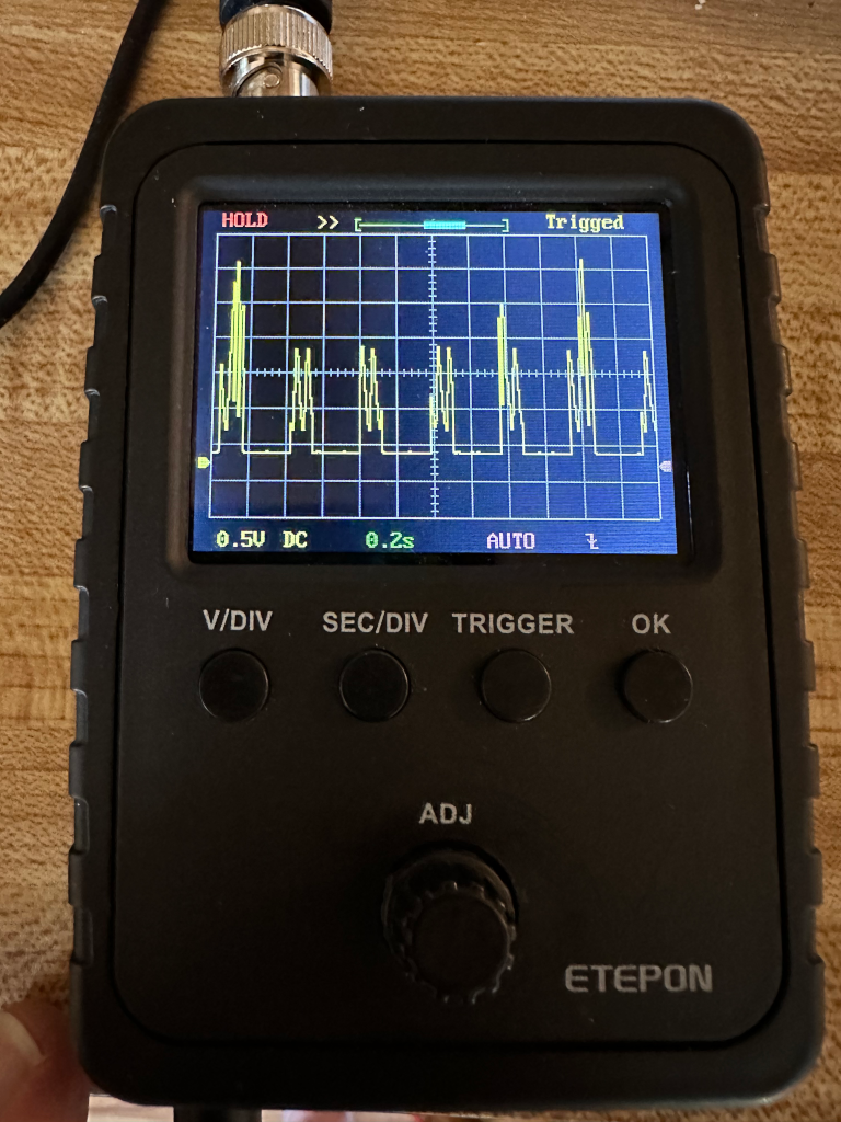
9/27 I watched a video about coding for WS2812b strips and the guy used an oscilloscope to check on his timing for the serial data line. I knew I had one in my stash and got it out only to find that it was not working. It turns out that the power jack had come off due to cold solder joints. A quick solder job fixed that.

ETEPON Oscilloscope working again after re-soldering the power input jack. Showing WS2812B serial.

9/28 I had tried to just run a serial high low imitating the control of the LED strip. I was making the switches change too fast. When I tried checking the results on the oscilloscope it could not keep up. I put the original code from Vivonomicron back onto the icebreaker and tested it with the oscilloscope. I decided to comment his code as heavily as I could.

While commenting on the code I tried having the color of the second be a different color. When the first 24 bits passed I changed the color. Uploading the code showed all of the pixels to be the second color. That’s when I realized that it is running in a loop. Pixels 0 through 10, over and over. Once the color changes it refreshes all of the pixels.

To fix the colors changing I had to enact the change for 1 through 10 and back to the original for pixel 0. That worked. Then I decided to remove those color changing lines of code and use a case statement. That worked exactly as I had imagined. Having good results after so much misses feels good.

Here is the edited code so far.

// Cause yosys to throw an error when we implicitly declare nets
// `default_nettype none

// Project entry point
module top (
	input  CLK,
	input  BTN_N, BTN1, BTN2, BTN3,
	output LED1, LED2, LED3, LED4, LED5,
	output P1B1,
);
	// Neopixel state machine.
  reg [2:0] state;
  reg [1:0] npxc;
  reg [12:0] lpxc;
  reg [7:0] bits;
  reg [7:0] led_num;
  reg [24:0] test_color = 24'b000000010000000100000000;
	reg [1:0] isiton;
	assign LED1 = 1'b0;
	assign LED2 = 1'b0;
	assign LED3 = 1'b0;
	assign LED4 = 1'b0;
	assign LED5 = 1'b0;
	assign P1B1 = isiton;

	always @(posedge CLK) begin
		// Process the state machine; states 0-3 are the four WS2812B 'ticks',
		// each consisting of 83.33 * 4 ~= 333.33 nanoseconds. Four of those
		// ticks are then ~1333.33 nanoseconds long, and we can get close to
		// the ideal 1250ns period.
		// A '1' is 3 high periods followed by 1 low period (999.99/333.33 ns)
		// A '0' is 1 high period followed by 3 low periods (333.33/999.99 ns)

		if (state == 0 || state == 1 || state == 2 || state == 3)
			begin									// run this for 3 times then increase state
				npxc = npxc + 1;
				if (npxc == 0)
					begin
						state = state + 1;
					end
			end // end of states 0, 1, 2, OR 3
		if (state == 4) // increases bits then if 24 set to 0 and increase state to 5, if <24 state = 0
			begin
				bits = bits + 1;
				if (bits == 24)
					begin
						bits = 0;
						state = state + 1;
					end
				else
					begin
						state = 0;
					end
			end // end of state 4
		if (state == 5) // go to the next pixel on the strip. if it is at the end state = 6, otherwise state = 0
			begin
				led_num = led_num + 1;
				case (led_num)
				1:	test_color = 24'b000000001000000000000000;
				2:	test_color = 24'b000000001000000000010000;
				3:	test_color = 24'b000000001000000010000000;
				4:	test_color = 24'b000000000000000010000000;
				5:	test_color = 24'b100000000000000010000000;
				6:	test_color = 24'b100000000000000000000000;
				7:	test_color = 24'b100000001000000000000000;
				default: test_color = 24'b100000001000000000000000;
				endcase
				if (led_num == 10)
					begin
						led_num = 0;
						state = state + 1;
					end
				else
					begin
						state = 0;
					end
			end // end of state 5
		if (state == 6) // This is a 12 bit counter sending 0 out the serial indicating reset of the strip
			begin					// it lasts for >80µs meaning that the end of the pixel numbers has been reached
				lpxc = lpxc + 1;
				if (lpxc == 0)
					begin
						state = 0;
					end
			end // end of state 6
		// Set the correct pin state.
		if (test_color & (1 << bits)) // if the current bit of test_color is 1, or ON, serial is high
			begin
			if (state == 0 || state == 1 || state == 2) //  run three cycles of high for pixel ON
				begin
					isiton <= 1;
				end
			else if (state == 3 || state == 6) // run one cycle of low for pixel ON
				begin
					isiton <= 0;
				end
			end // end of testing the & bit is 1. If the current bit is 0, or OFF, serial is low.
		else
			begin
			if (state == 0) // run one cycle of high for pixel OFF
				begin
					isiton <= 1;
				end
			else if (state == 1 || state == 2 || state == 3 || state == 6) // run three cycles of low for pixel off
				begin
					isiton <= 0;
				end
		end // end of testing the & bit is 0
	end

endmodule

Next I want to see if I can animate the pixels. That’ll have to happen in a while since I have chores to do right now.

Icebreaker FPGA workshop

I have been working through the icebreaker workshop from Workshop. On the next to the last is a list of optional things to attempt. I decided to change the display to show something other than numbers. I tried Japanese numbers on a 7-segment display even though there are not enough segments to do this justice. With that working I thought “what about having a button toggle between Western and Japanese numbers. This is where I hit a brick wall.

I am at the beginning stages of learning Verilog and HDL. I was thinking of modules as functions. It took a wake up yesterday morning I was thinking programming and not hardware design. I wasn’t passing a variable from one function to the next. I didn’t need global variables. I needed to have wires and inputs and outputs. However, just because I had this realization didn’t mean I knew how to implement it. Looking up errors and warnings on the web AND understanding the answers in blogs and forums was difficult. It was like a foreign language.

I was running into “unconstrained”, “has no driver”, and “implicitly declared”, among others. When I thought I understood how to fix the error or warning I would just move it to another line of code.

I finally got the code for the stopwatch to do what I wanted.
Button 3 starts or stops the count running.
Button 2 pauses and flashes the display.
Button 3 toggles the set of characters to display.
Button N stops the count and sets it back to zero.

(Now I am going to try and paste the entire code in one block without having to deal with it separating itself into multiple block paragraphs.)

// Cause yosys to throw an error when we implicitly declare nets
// `default_nettype none

// Project entry point
module top (
	input  CLK,
	input  BTN_N, BTN1, BTN2, BTN3,
	output LED1, LED2, LED3, LED4, LED5,
	output P1A1, P1A2, P1A3, P1A4, P1A7, P1A8, P1A9, P1A10,
);
	// 7 segment control line bus
	wire [7:0] seven_segment;

	// Assign 7 segment control line bus to Pmod pins
	assign { P1A10, P1A9, P1A8, P1A7, P1A4, P1A3, P1A2, P1A1 } = seven_segment;

	// Display value register and increment bus
	reg [7:0] display_value = 0;
	wire [7:0] display_value_inc;

	// Lap registers
	reg [7:0] lap_value = 0;
	reg [4:0] lap_timeout = 0;
	reg [7:0] flasher_temp;
	reg [2:0] flasher_tick = 0;

	// Clock divider and pulse registers
	reg [20:0] clkdiv = 0;
	reg clkdiv_pulse = 0;
	reg running = 0;
	reg debounce3 = 0;
	reg [2:0] num_choice = 0;
	reg debounce1 = 0;

	wire dragon;

	assign dragon = num_choice;

	reg [23:0] counter = 1'b0;
	reg [4:0] pulsar = 0;
	reg [1:0] lit1 = 1'b0;
	reg [1:0] lit2 = 1'b0;
	reg [1:0] lit3 = 1'b0;
	reg [1:0] lit4 = 1'b0;
	reg [1:0] lit5 = 1'b0;

	assign LED1 = lit1;
	assign LED2 = lit2;
	assign LED3 = lit3;
	assign LED4 = lit4;
	assign LED5 = lit5;

	always @(posedge CLK) begin
		counter++;
		if (counter > 800000) begin
			counter = 0;
			pulsar++;
			if (pulsar > 3) begin
				pulsar = 0;
			end
		end
		case (pulsar)
		0: begin
			lit2 = 1'b1;
			lit4 = 1'b0;
			end
		1: begin
			lit2 = 1'b0;
			lit5 = 1'b1;
			end
		2: begin
			lit5 = 1'b0;
			lit3 = 1'b1;
			end
		3: begin
			lit3 = 1'b0;
			lit4 = 1'b1;
			end
		default: lit5 = 1'b0;
		endcase
	end

	// Synchronous logic
	always @(posedge CLK) begin
		// Clock divider pulse generator
		if (clkdiv == 1200000) begin
			clkdiv <= 0;
			clkdiv_pulse <= 1;
		end else begin
			clkdiv <= clkdiv + 1;
			clkdiv_pulse <= 0;
		end

		// Lap Timeout counter
		if (clkdiv_pulse && lap_timeout) begin
			lap_timeout <= lap_timeout -1;
			if (flasher_tick) begin
				lap_value = 8'b11111111;
				flasher_tick = 0;
			end else begin
				lap_value = flasher_temp;
				flasher_tick = 1;
			end
		end

		// Timer counter
		if (clkdiv_pulse && running) begin
			display_value <= display_value_inc;
		end

		// Button controls
		if (!BTN_N) begin
			display_value <= 0;
			running = 0;
			lap_timeout <= 0;
		end

		if (!BTN3) debounce3 = 0;

		if (BTN3) begin
			if (debounce3 == 0) begin
				debounce3 = 1;
				if (running) running = 0;
				else running = 1;
			end
		end

		if (!BTN1) debounce1 = 0;

		if (BTN1) begin
			if (!debounce1) begin
				debounce1 = 1;
				if (num_choice) num_choice = 0;
				else num_choice = 1;
			end
		end

		if (BTN2) begin
			lap_value <= display_value;
			flasher_temp <= display_value;
			lap_timeout <= 20;
		end

	end

	// assign display_value_inc = display_value + 8'b1;  // take this out for bcd8_increment
	// make instance of BCD counter
	bcd8_increment increment1 (
		.din(display_value),
		.dout (display_value_inc)
	);

	// 7 segment display control Pmod 1A
	seven_seg_ctrl seven_segment_ctrl (
		.CLK(CLK),
		.din(lap_timeout ? lap_value[7:0] : display_value[7:0]),
		.dout(seven_segment),
		.dragon(dragon),
	);

endmodule // End of the Top module

// BCD (Binary Coded Decimal) counter
module bcd8_increment (
	input [7:0] din,
	output reg [7:0] dout
);
	always @* begin
		case (1'b1)
			din[7:0] == 8'h 99:
				dout = 0;
			din[3:0] == 4'h 9:
				dout = {din[7:4] + 4'd 1, 4'h 0};
			default:
				dout = {din[7:4], din[3:0] + 4'd 1};
		endcase
	end
endmodule

// Seven segment controller
// Switches quickly between the two parts of the display
// to create the illusion of both halves being illuminated
// at the same time.
module seven_seg_ctrl (
	input CLK,
	input [7:0] din,
	input dragon,
	output reg [7:0] dout
);
	wire [6:0] lsb_digit;
	wire [6:0] msb_digit;

	seven_seg_hex msb_nibble (
		.dragon(dragon),
		.din(din[7:4]),
		.dout(msb_digit)
	);

	seven_seg_hex lsb_nibble (
		.dragon(dragon),
		.din(din[3:0]),
		.dout(lsb_digit)
	);

	reg [9:0] clkdiv = 0;
	reg clkdiv_pulse = 0;
	reg msb_not_lsb = 0;

	always @(posedge CLK) begin
		clkdiv <= clkdiv + 1;
		clkdiv_pulse <= &clkdiv;
		msb_not_lsb <= msb_not_lsb ^ clkdiv_pulse;

		if (clkdiv_pulse) begin
			if (msb_not_lsb) begin
				dout[6:0] <= ~msb_digit;
				dout[7] <= 0;
			end else begin
				dout[6:0] <= ~lsb_digit;
				dout[7] <= 1;
			end
		end
	end
endmodule

// Convert 4bit numbers to 7 segments
module seven_seg_hex (
	input dragon,
	input [3:0] din,
	output reg [6:0] dout
);

reg num_choice = dragon;

	always @*
		case (din)
			4'h0: begin
				if (num_choice) dout = 7'b 1011100;
				else dout = 7'b0111111;
				end
			4'h1: begin
				if (num_choice) dout = 7'b 1000000;
				else dout = 7'b0000110;
				end
			4'h2: begin
				if (num_choice) dout = 7'b 0001001;
				else dout = 7'b1011011;
				end
			4'h3: begin
				if (num_choice) dout = 7'b 1001001;
				else dout = 7'b1001111;
				end
			4'h4: begin
				if (num_choice) dout = 7'b 0111111;
				else dout = 7'b1100110;
				end
			4'h5: begin
				if (num_choice) dout = 7'b 1111101;
				else dout = 7'b1011011;
				end
			4'h6: begin
				if (num_choice) dout = 7'b 0010101;
				else dout = 7'b1111101;
				end
			4'h7: begin
				if (num_choice) dout = 7'b 1111000;
				else dout = 7'b0000111;
				end
			4'h8: begin
				if (num_choice) dout = 7'b 0110110;
				else dout = 7'b1111111;
				end
			4'h9: begin
				if (num_choice) dout = 7'b 1110100;
				else dout = 7'b1101111;
				end
			4'hA: dout = 7'b 1110111;
			4'hB: dout = 7'b 1111100;
			4'hC: dout = 7'b 0111001;
			4'hD: dout = 7'b 1011110;
			4'hE: dout = 7'b 1111001;
			4'hF: dout = 7'b 0000000;
			default: dout = 7'b 0000000;
		endcase
endmodule

The icebreaker workshop is being quite the adventure. I think I could join an online Verilog/Yosys forum, but I don’t have enough experience to be able to ask the right questions. Perhaps I will join one once I understand the terminology better.

FPGA programming is an adventure

I bought an icebreaker FPGA to learn some more programming. I had been using the 2019 Supercon badge. Esden had penned the workshops for learning programming on both of the devices. The “additional things to explore” are fun to figure out.

Presently I am at 50% completion of the tasks. The next one to tackle will be displaying something other than numbers. Well, I am going to try to draw Japanese numbers on the 7-segment display. There is not enough detail to make correct numbers, such as the 4. I’ll do it anyway.

I ran into a problem while making the BTN3 become a toggle for starting and stopping the display running. I would not have noticed it if I hadn’t checked that all of the other parts of the code were working properly. Pressing BTN_N is supposed to stop the counting and reset the numbers back to zero. That was no longer happening.

if (!BTN_N) begin
  display_value <= 0;
  running <= 0;
  lap_timeout <= 0;
end

if (!BTN3) debounce3 = 0;

if (BTN3) begin
  if (debounce3 == 0) begin
    debounce3 = 1;
    if (running) running = 0;
  else running = 1;
  end
end

While attempting to figure out what was going wrong I commented out lines or whole sections. BTN1 had been set to start the counter running. I had commented it out. I had to put it back in, but this time to stop the counting. When the counting was stopped pressing the BTN_N would work. It took quite a bit of head scratching and testing before I realized that the block for if (!BTN_N) begin should have running = 0; and not <=!

When the ‘light’ comes on, is it an LED? Part 2

In the previous article (I am adding a link so the analysis will be happier) Part 1 I discussed my troubles trying to blink an LED on the Hackaday 2019 Badge. I decided to post the full FPGA code that finally works. I got two different versions.

After getting proper results with the one code, I decided to try out the different way. The assign ledc[5] = 1'b1; to turn on the LED at start was my problem all along.

Here are the two successful FPGA codes.

module top (
input clk,
output [10:0] ledc,
output [2:0] leda,
);

assign leda = 3'b010;

assign ledc[5] = counter[21];

reg [31:0] counter;

initial begin
counter <= 32'b0;
end

always @(posedge clk) begin
counter <= counter + 1'b1;
end

endmodule

ADM! That was difficult to type into one paragraph! Copy and paste was not going to work. And the second FPGA code is below.

module top (
input clk,
output [10:0] ledc,
output [2:0] leda,
);

assign leda = 3'b010;
assign ledc[5] = led_status;

reg [31:0] counter;
reg led_status;

initial begin
counter <= 32'b0;
led_status = 1'b0;
end

always @(posedge clk) begin
counter <= counter + 1'b1;
if (counter > 5000000) begin
led_status <= !led_status;
counter <= 32'b0;
end
end

endmodule

That was a little bit easier, but copy and paste got rid of a lot of the returns at the end of lines. I had to shift-return a bunch of times. Adding FPGA code to this post hasn’t been easy.

When the ‘light’ comes on, is it an LED?

A couple days ago I decided to try to blink an LED on the 2019 Hackaday Supercon badge. I tried and failed with many iterations of what I thought would work easily. Yesterday I decided to look up a blink example on the web to see how they were doing it. I could not get any of them to work. What was I doing wrong?

This morning as I was making coffee (pour-over) I started thinking about what I should try next. I have a counter that when it gets to 500000 it should turn on the LED. However, I already have the LED on. So, I decided to turn off the LED when the counter got up to 500000. I didn’t notice in the nesting that counter got reset to 0 (32’b0) in the wrong place and would add on and reset to zero right away. ::smack forehead::

always @(posedge clk) begin
counter <= counter + 1'b1;
if (counter > 500000) begin
ledc[5] = 1'b0;
end else begin
ledc[5] = 1'b1;
end
counter <= 32'b0;
end

Even when I took moved the reset of the counter to the proper place the LED would not turn off when counter reached 500000. UGH!, because of the else! OK time to change the if statement to if (counter[28]). Still the LED would not turn off.

Poured the first cup of coffee and finished pouring water over the grounds. Caffeine must be helping, change the code to

always @(posedge clk) begin
counter <= counter + 1'b1;
end


always @(posedge clk) begin

if (counter > 500000)begin
ledc[5] = 1'b1;
end else begin
ledc[5] = 1'b0;
end

That seemed to look OK, but it still didn’t turn off the LED until the the counter got above 500000. Was the clock speed so fast that it got to 500000 too quickly? How about resetting counter when it got to one million? That way the light should be off until 500001 and then back on. Right? … Nope! The LED was still not turning off. Whether I started with the LED off or on the counter would not make a change to the LED.

In a workshop code they assigned LEDs to come on with button presses. Something like press button one and turn on LED 2. When you released the button the LED turned off. They used assign ledc[2] = btn[1]; , and I was using assign ledc[5] = 1'b1; to initialize LED 5 to be on at start up.

I tried many different iterations of if (counter > 500000) and if counter[28] that didn’t work to turn off the LED. The ‘light’ came on above my head while thinking about how they were toggling the LED with a button. I decided to try it sort of like I thought they were doing.

assign ledc[5] = counter[21];

always @(posedge clk) begin
counter <= counter + 1'b1;
end

This worked just fine. The LED number 5 was blinking its fool head off.

A little bit more experimenting is going to help me figure out why trying to use the counter with an if statement would not work. I am starting to think that it is because of the assign command.