
I am going to try to get a string of WS2812B RGB LEDs (NeoPixels) to display using the Icebreaker FPGA board.
Last night I figured out the DIP Switch PMOD. I chose switch 1 to control an LED on the Icebreaker. After messing with the easy stuff I decided to have switch 8 to spin the little ring of LEDs clockwise or counter-clockwise. That took a bit of time to figure out that the case statement for displaying the LEDs could not start with 0 because when subtracting you can’t check if (variable < 0) with the way I have the code set up. So, I made the case start with 1 through 4 instead of 0 through 3.
9/24 – I have been messing with code from Vivonomicron’s page. Parts of it is very understandable, while other parts elude me. The code takes a bit from a 24-bit register and sets a time to the WS2812b NeoPixel strip. I did find out that the 24 bits are 8-8-8 and Blue-Red-Green. Within the eight bits for a color the left most bit is dim and the right most bit is bright. At least now I am not blinded while attempting to figure out this code example.
I have a strip of about 28 NeoPixels. At this time I am only coding for 10 of them. Some of the time eleven of them turn on. It might be the way the program is written. I haven’t made big changes to it, yet. It is only showing one color per NeoPixel and I am going to attempt to have different colors and perhaps some of them off.
9/25 – Working with the to figure out a way to make my own code so it’ll allow me to control the WS2812b pixels individually is just a little strange. When I think I have a grasp on the timing and try it out I don’t get the expected results. Quite a few of the times when I upload the code a second time another pixel gets added to the mix. I think that is because the strip is skipping the first pixel. Also, some of the time when I try to light up a couple of the pixels to be red and they don’t show up correctly I can unplug and re-plugin the board. However, this time the two pixels are offset and Blue!
I am going to keep mashing away at this until I can do what I need. Orchestra rehearsals and practice is getting in the way.
9/27 I watched a video about coding for WS2812b strips and the guy used an oscilloscope to check on his timing for the serial data line. I knew I had one in my stash and got it out only to find that it was not working. It turns out that the power jack had come off due to cold solder joints. A quick solder job fixed that.
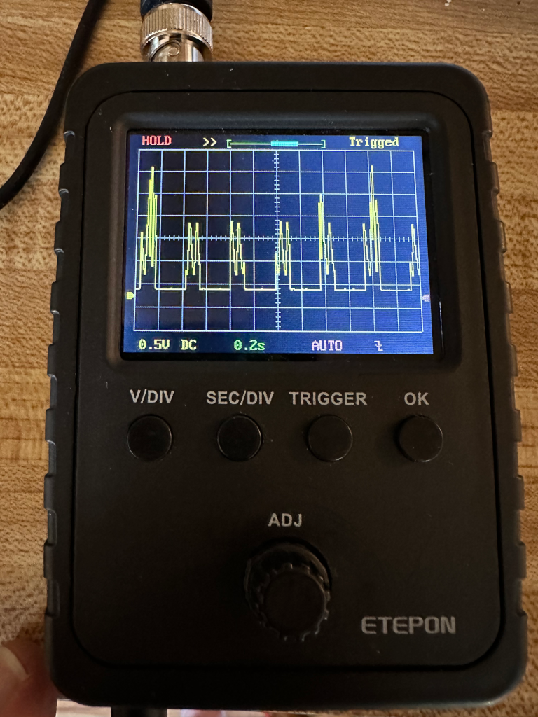
9/28 I had tried to just run a serial high low imitating the control of the LED strip. I was making the switches change too fast. When I tried checking the results on the oscilloscope it could not keep up. I put the original code from Vivonomicron back onto the icebreaker and tested it with the oscilloscope. I decided to comment his code as heavily as I could.
While commenting on the code I tried having the color of the second be a different color. When the first 24 bits passed I changed the color. Uploading the code showed all of the pixels to be the second color. That’s when I realized that it is running in a loop. Pixels 0 through 10, over and over. Once the color changes it refreshes all of the pixels.
To fix the colors changing I had to enact the change for 1 through 10 and back to the original for pixel 0. That worked. Then I decided to remove those color changing lines of code and use a case statement. That worked exactly as I had imagined. Having good results after so much misses feels good.
Here is the edited code so far.
// Cause yosys to throw an error when we implicitly declare nets
// `default_nettype none

// Project entry point
module top (
	input  CLK,
	input  BTN_N, BTN1, BTN2, BTN3,
	output LED1, LED2, LED3, LED4, LED5,
	output P1B1,
);
	// Neopixel state machine.
  reg [2:0] state;
  reg [1:0] npxc;
  reg [12:0] lpxc;
  reg [7:0] bits;
  reg [7:0] led_num;
  reg [24:0] test_color = 24'b000000010000000100000000;
	reg [1:0] isiton;
	assign LED1 = 1'b0;
	assign LED2 = 1'b0;
	assign LED3 = 1'b0;
	assign LED4 = 1'b0;
	assign LED5 = 1'b0;
	assign P1B1 = isiton;

	always @(posedge CLK) begin
		// Process the state machine; states 0-3 are the four WS2812B 'ticks',
		// each consisting of 83.33 * 4 ~= 333.33 nanoseconds. Four of those
		// ticks are then ~1333.33 nanoseconds long, and we can get close to
		// the ideal 1250ns period.
		// A '1' is 3 high periods followed by 1 low period (999.99/333.33 ns)
		// A '0' is 1 high period followed by 3 low periods (333.33/999.99 ns)

		if (state == 0 || state == 1 || state == 2 || state == 3)
			begin									// run this for 3 times then increase state
				npxc = npxc + 1;
				if (npxc == 0)
					begin
						state = state + 1;
					end
			end // end of states 0, 1, 2, OR 3
		if (state == 4) // increases bits then if 24 set to 0 and increase state to 5, if <24 state = 0
			begin
				bits = bits + 1;
				if (bits == 24)
					begin
						bits = 0;
						state = state + 1;
					end
				else
					begin
						state = 0;
					end
			end // end of state 4
		if (state == 5) // go to the next pixel on the strip. if it is at the end state = 6, otherwise state = 0
			begin
				led_num = led_num + 1;
				case (led_num)
				1:	test_color = 24'b000000001000000000000000;
				2:	test_color = 24'b000000001000000000010000;
				3:	test_color = 24'b000000001000000010000000;
				4:	test_color = 24'b000000000000000010000000;
				5:	test_color = 24'b100000000000000010000000;
				6:	test_color = 24'b100000000000000000000000;
				7:	test_color = 24'b100000001000000000000000;
				default: test_color = 24'b100000001000000000000000;
				endcase
				if (led_num == 10)
					begin
						led_num = 0;
						state = state + 1;
					end
				else
					begin
						state = 0;
					end
			end // end of state 5
		if (state == 6) // This is a 12 bit counter sending 0 out the serial indicating reset of the strip
			begin					// it lasts for >80µs meaning that the end of the pixel numbers has been reached
				lpxc = lpxc + 1;
				if (lpxc == 0)
					begin
						state = 0;
					end
			end // end of state 6
		// Set the correct pin state.
		if (test_color & (1 << bits)) // if the current bit of test_color is 1, or ON, serial is high
			begin
			if (state == 0 || state == 1 || state == 2) //  run three cycles of high for pixel ON
				begin
					isiton <= 1;
				end
			else if (state == 3 || state == 6) // run one cycle of low for pixel ON
				begin
					isiton <= 0;
				end
			end // end of testing the & bit is 1. If the current bit is 0, or OFF, serial is low.
		else
			begin
			if (state == 0) // run one cycle of high for pixel OFF
				begin
					isiton <= 1;
				end
			else if (state == 1 || state == 2 || state == 3 || state == 6) // run three cycles of low for pixel off
				begin
					isiton <= 0;
				end
		end // end of testing the & bit is 0
	end

endmodule
Next I want to see if I can animate the pixels. That’ll have to happen in a while since I have chores to do right now.