
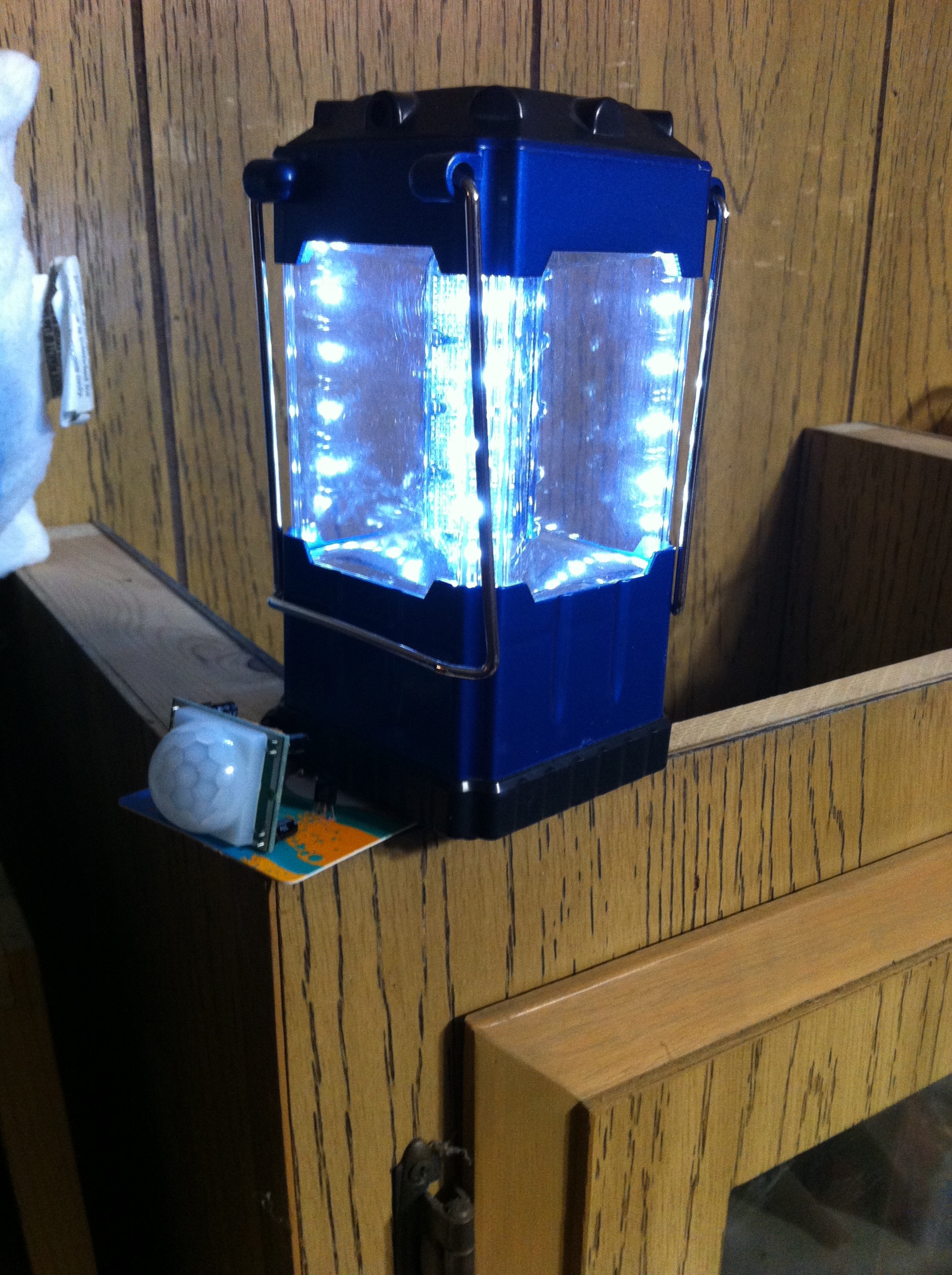
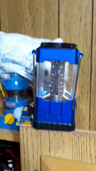
I wanted to be able to have an electric lantern turn on as I entered the room. I decided to use a PIR sensor (Pyroelectric (“passive”) InfraRed sensor) as the detector. First I had to use a breadboard and the parts to get it worked out.
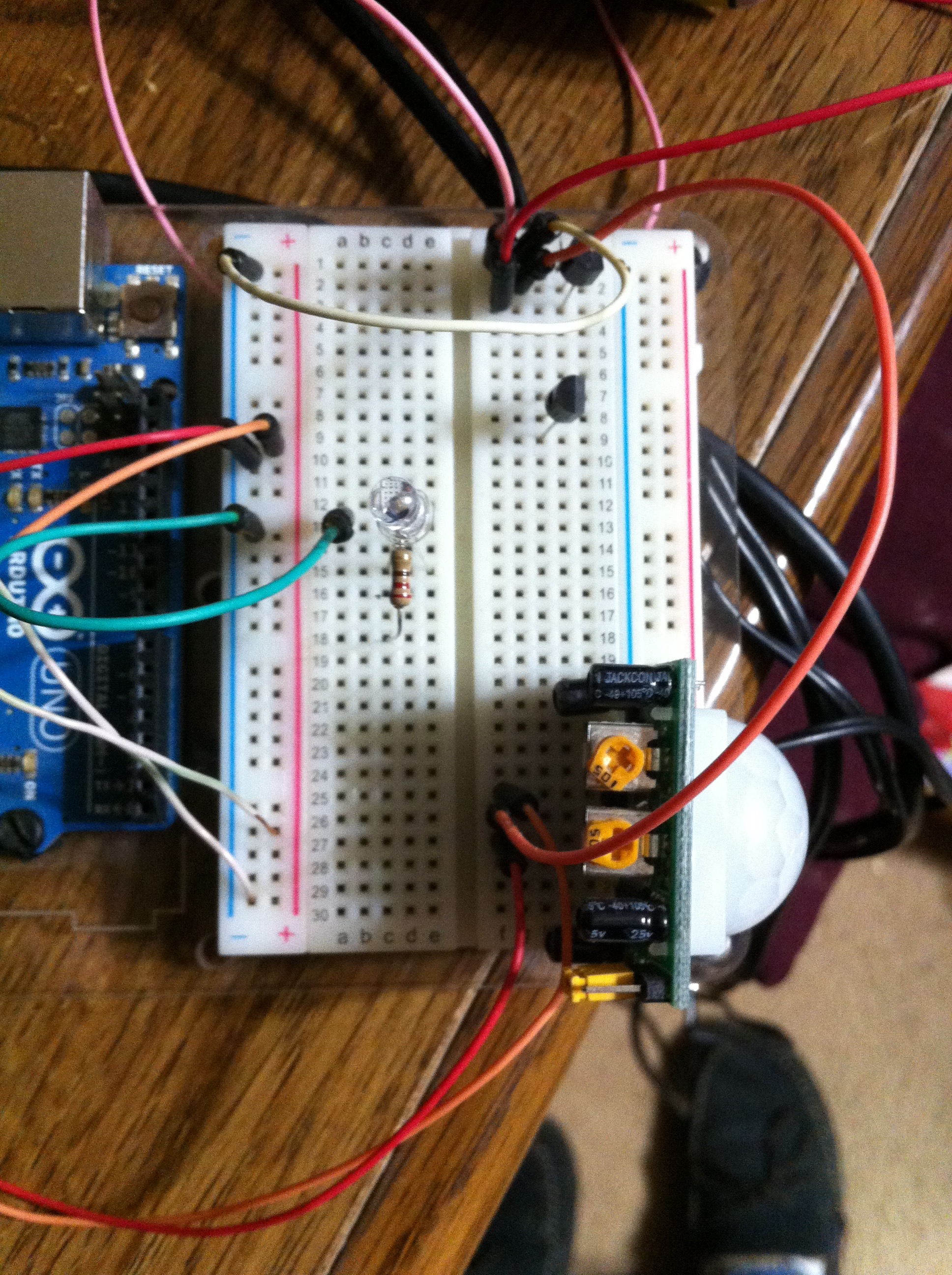
There is a second transistor on the breadboard as well as an LED and resistor. I didn’t use these in the project. They were left over from an Arduino project.
I am powering the PIR with 5v from a USB phone charger. The three AAA batteries inside the lantern will light up the lantern’s LEDs.
A PIR has three pins. DC+ in, Output, and Ground (-). I connected the Output pin to the Base of the transistor. At first I used a 2n3904 transistor. This worked will when I as just using an LED on the breadboard as the light. When I hooked up the lantern there was too much power and it bled through.
I put a guitar pick between one of the batteries on the positive side and put wires from the battery and the post where it was to touch. It was like adding a switch. The 2n3904 didn’t stop the electricity from flowing. I had a 2n2222 on hand and ready that it can handle about three times as much and the 2n3904.
The schematic ends up looking something like this picture.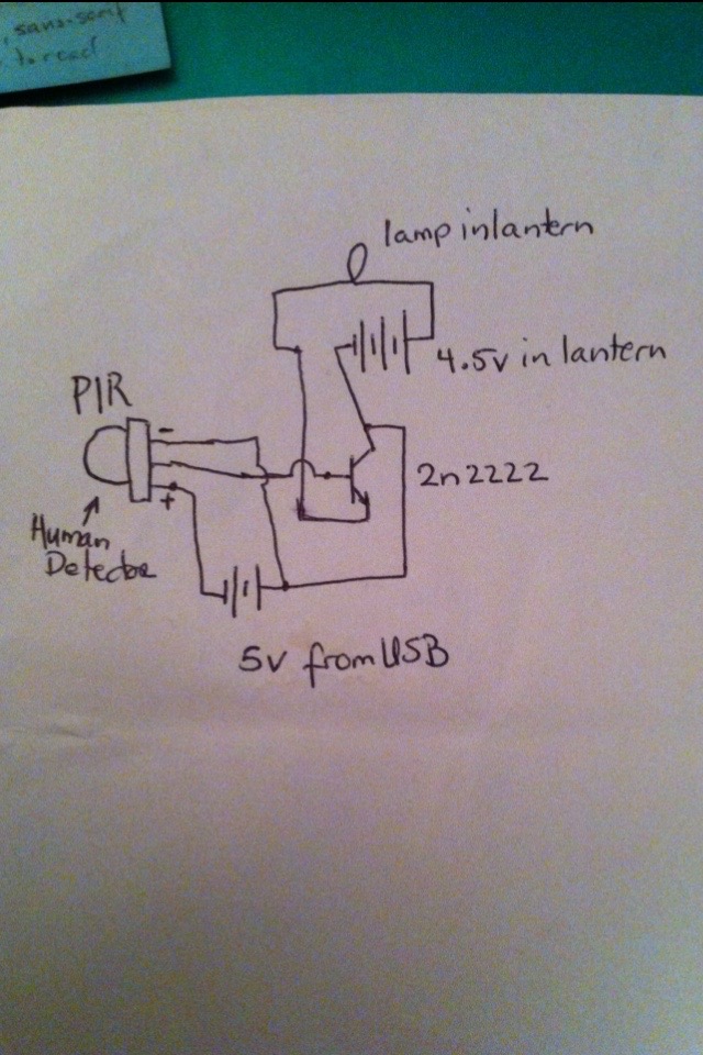
Perhaps I should be using a resistor between the PIR and the Base of the transistor. So far the transistor doesn’t seem to get hot or mind.
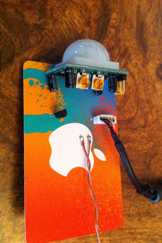
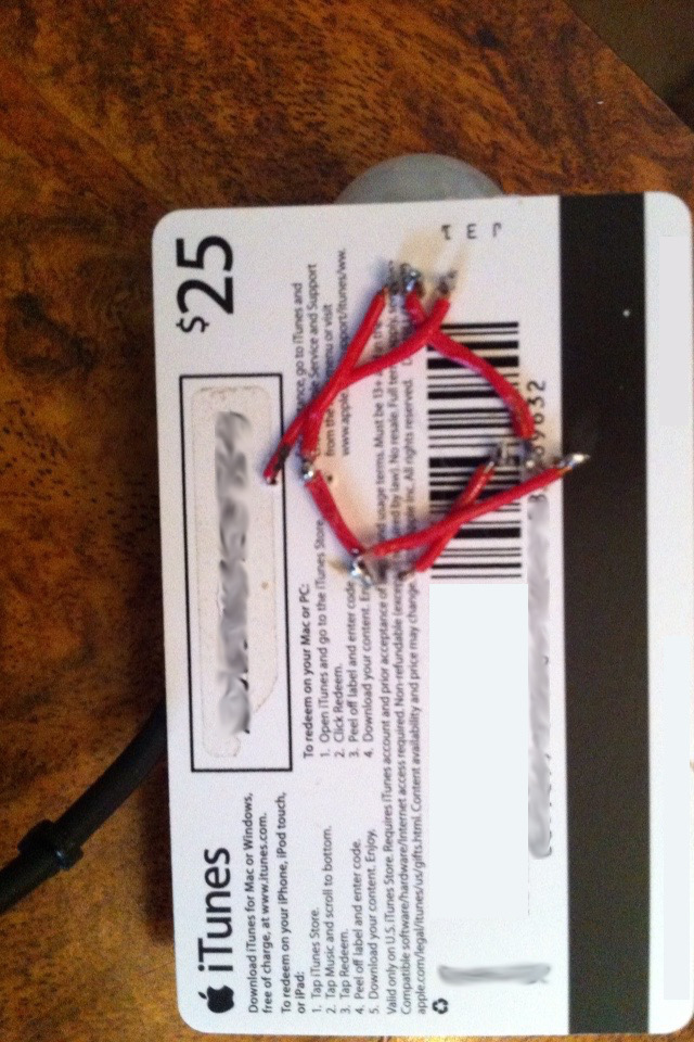
Once I had the design working I had to solder everything together. I could not find an electronics board with all the holes pre-drilled. I knew I have one somewhere. I decided to use an old iTunes gift card as the circuit board. I drilled holes in it for the PIR’s pins, as well as for the transistor. I used short jumper wires to create the wiring I wanted. To connect the DC + and – pins of the PIR I soldered short wires to them and poked the other ends up through holes drilled in the card. I used a USB cable taken from a broken mouse and plugged it in onto the exposed pins I just created. For the fires running to the lantern I soldered two wires to the collector and emitter of the transistor and poked the other ends up through the card. I then soldered longer wires to those newly created pins.
Now came the tricky part. I took a small piece of an expired credit card and glued aluminum foil on both sides. After the super glue was dry I checked to see that the foil was not touching from one side to the other. I soldered the two long wires to the aluminum, one per side. Now I had a separator that I would be able to use inside the battery case of the lantern. I removed one of the batteries from the lantern and put this little piece at the positive end of the battery while I reinserted the battery. I think using a copper clad circuit board would have been easier to work with. You know the kind I mean, copper on both sides so you can etch your own designs with some acid. I think the closest store that might have this in stock, on short notice, is about 45 miles away.
I read information about the PIR from Adafruit. (www.adafruit.com) I love the NeoPixel LEDs they sell. They are easily programmed and are very bright.
After learning more about transistors, I now know that I need to include some resistors in this circuit. I’m going to have to do some calculations and add them in. – Greg