
It took me days to figure out how to program an ESP8266 with an FTDI connector. I finally got it figured out last night. I remember using an Arduino Uno to program them a little over a year ago. I’ll have to try that again sometime soon.
The two FTDI boards(? cards? devices?) that I have look different but, essentially, are the same. I have one 3.3v from Sparkfun.
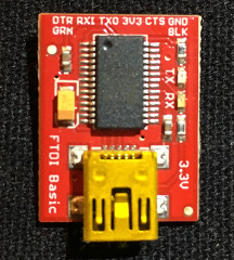

On the back side it looks like you’d be able to solder a jumper wire across the little pads to make it either 3.3v or 5v. I am not sure and don’t feel like burning it up just to see.
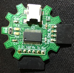
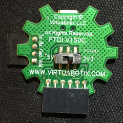
The second one is from Virtuabotix. It has a switch on the back side so you can choose either 3.3v or 5v. There are also two connectors that you can use, four pins or six pins.
You actually only have to use four of the pins on the FTDI to program the ESP8266-01, voltage out (VDD or 3.3v), GND, RX, and TX.
I found it much easier to use a little homemade breadboard header while programming or just messing around with the ESP8266-01. The
ESP8266-01 by itself is not breadboard friendly. I ended up taking a row of header pins and cut them into 4 pin lengths. I then glued them together to make a 2×4 header row that I could plug the ESP8266-01 into. I bent the rows of the pins outward, away from the opposite side, and then back vertical so they would fit into a breadboard across that little trough that separates the two sides of the breadboard. You have to keep messing with the angles of the wires to get the pins into the correct position. It doesn’t take too awful much time to get it correct.
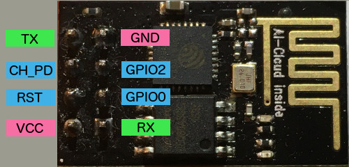
There are eight pins on the ESP8266-01. You only need to hook up six of the pins on the ESP8266-01 to four of the FTDI pins.
If you look closely you will notice on the Sparkfun FTDI the six pins are labeled GND, CTS, 3v3, TX0, RX1, and DTR. On the Virtuabotix FTDI the six pins are labeled G, D1, Vdd, Rx, Tx, and Rst. The second set of four pins on the Virtuabotix are labeled Vdd, Gnd, Rx, and Tx. We are going to use only four of the pins on the FTDI. The four pin connection on the Virtuabotix FTDI already has the only ones we need. The ones on the six pin connectors that we will use are ground (G or GND), voltage (3v3, or Vdd), receive (Rx or RX1) and transmit (Tx or TX0). You may have a board that has different pin labeling, but they should be the same and in the same order. That is, if the company followed the same building convention as these two companies.
Since you will need to use six of the pins on the ESP8266-01 and only four of the FTDI pins it is easier to use a breadboard. The pin wiring will be:
FTDI -> ESP8266-01
GND -> GND and GPIO0 (this is ground)
3v3 -> VCC and CH_PD (this is voltage)
RX -> RX
TX -> TX
Both the ground and voltage pins of the FTDI go to two pins on the ESP8266-01.
Once you have the two devices hooked together you can plug in the FTDI to your computer and upload a program to the ESP8266-01.
I used the Arduino IDE to program the ESP8266-01. I am familiar with the Arduino IDE so I use it.
Once you have the USB cable hooked up to your computer, in the Arduino IDE select Tools from the top menu. Select “Generic ESP8266 Module” for the Board. On version 1.6.5 of the Arduino IDE more options will show up under Tools. I have them set as the following:
Flash Mode: “DIO”
Flash Frequency: “40MHz”
Upload Using: “Serial”
CPU Frequency: “80MHz”
Flash Size: “512K (64K SPIFFS)”
Upload Speed; “115200”
For the Port you will need to select the port that your FTDI is using.
I modified the basic BLINK sketch to blink an LED for 1/10 of a second twice and half a second repeatedly. After you have the ESP8266-01 programmed you will need to disconnect the wiring for the FTDI. Then you will need to wire up the ESP8266-01 with battery + to VCC, and battery – to ground. I used two AA batteries for power. Also put a resistor from GPIO2 to an LED and the other leg of the LED to ground. There should also be a jumper between CH_PD and VCC so they both get power from the battery.
Here is a copy of the sketch that I modified slightly (you may use it and modify it):
/*

  Blink

  Turns on an LED on for one tenth of a  second

  then off for one tenth of a second

  then on for one tenth of a  second

  then off for one tenth of a second

  then on for half a second

  then off for half of a second

  repeatedly.
This example code is in the public domain.
*/
// Pin 13 has an LED connected on most Arduino boards.
// Pin 11 has the LED on Teensy 2.0
// Pin 6 has the LED on Teensy++ 2.0
// Pin 13 has the LED on Teensy 3.0
// Pin 2 for the ESP8266-01 and I put the LED on the breadboard
// for this device with a resistor to not burn out the LED.
// give it a name:
int led = 2;
// the setup routine runs once when you press reset:
void setup() {
// initialize the digital pin as an output.
pinMode(led, OUTPUT);
}
// the loop routine runs over and over again forever:
void loop() {
digitalWrite(led, HIGH); // turn the LED on (HIGH is the voltage level)
delay(100); // wait for a 1/4 second
digitalWrite(led, LOW); // turn the LED off by making the voltage LOW
delay(300); // wait for a 1/4 second
digitalWrite(led, HIGH);
delay(100);
digitalWrite(led, LOW);
delay(300);
digitalWrite(led, HIGH);
delay(500);
digitalWrite(led, LOW);
delay(500);
}
That’s about it for using an FTDI to program an ESP8266-01 using the Arduino software.